7-Segment LED Display with Proteus Simulation
Turning four input bits into ten digits with K-maps, then simulating the circuit in Proteus.

Phanith LIM
A 7-segment display shows a digit by lighting some of its seven bars. The question this project answers is a small one: given a number in binary, which bars should be on?
I built the answer as a logic circuit and simulated it in Proteus. This was for my mathematics class in my first year at the ITE Department, Faculty of Engineering, and it is still one of my favourite things I made that year. 😁
Seven questions, not one
The input is four bits, A B C D, enough to count from 0 to 15. The output is seven wires, one per segment, named a through g.
That means there is no single circuit to design. Each segment is its own yes-or-no question, asked of the same four inputs:
- Segment a is on for 0, 2, 3, 5, 6, 7, 8 and 9.
- Segment e is on for 0, 2, 6 and 8.
- And so on for the other five.
Seven segments, seven boolean functions, all sharing the same four input bits.
Where the don't-cares help
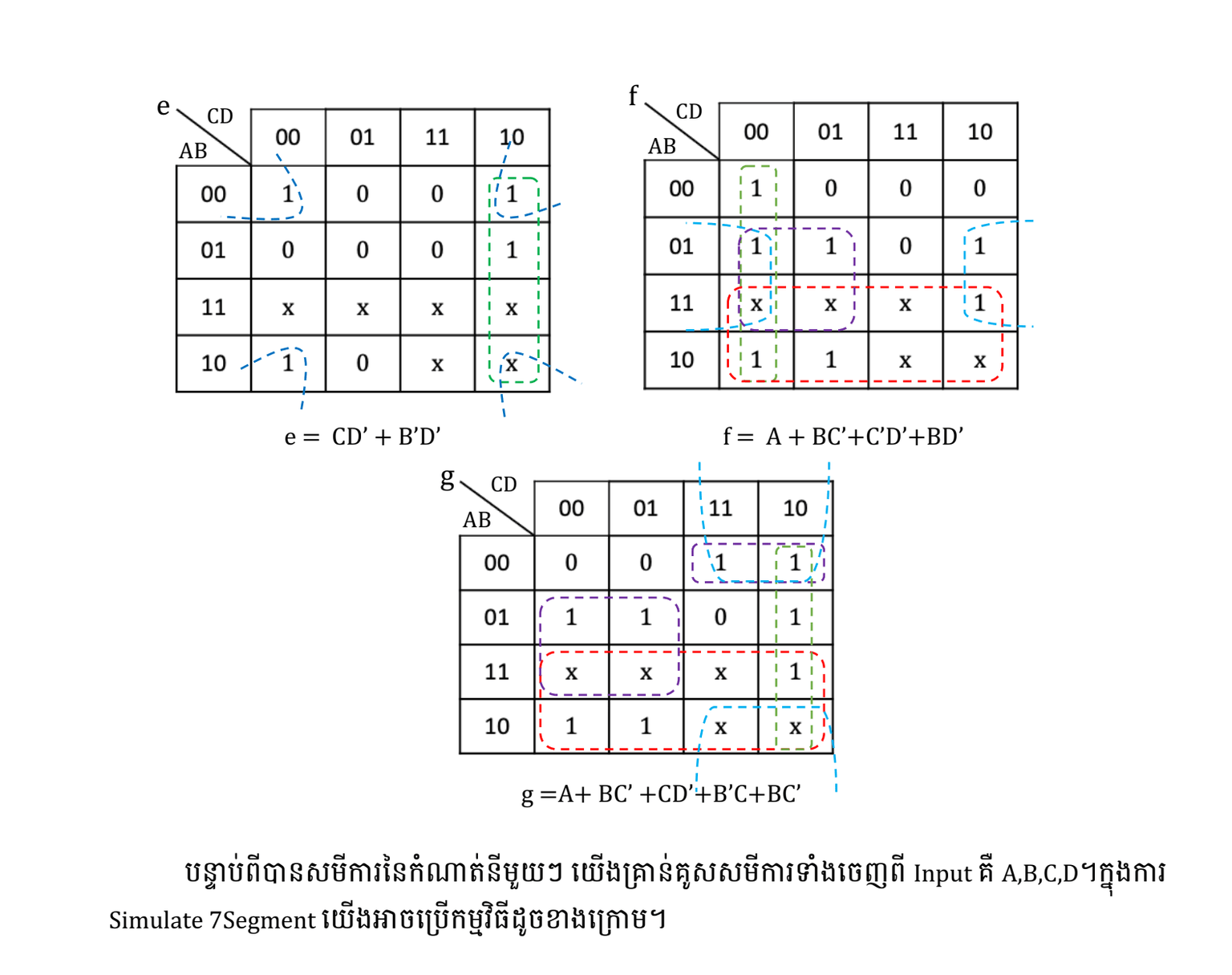
Four bits give sixteen combinations, but a digit only needs ten of them. The inputs for 10 to 15 never happen, so the output for those rows does not matter. On a Karnaugh map they are written as x, and that is where the simplification comes from: an x can be read as 1 when it helps a group grow, or ignored when it does not.
K-maps for segments e, f and g. The x cells are the inputs a digit never uses.
Grouping the cells gives a short expression for each segment:
e = CD' + B'D'
f = A + BC' + C'D' + BD'
Without the don't-cares these expressions would be noticeably longer, which means more gates to wire up. The same method gives a, b, c, d and g. All seven are worked out in the PDFs at the bottom.
Building it in Proteus
From there it is just construction. Each expression becomes a small arrangement of AND, OR and NOT gates, the seven outputs go to the seven segment pins, and four switches drive the input bits.
Proteus runs the whole thing without any hardware, so you can flip the input switches and watch the digit change. When a segment stays dark that should be lit, the mistake is either in the grouping on the K-map or in the wiring, and both are quick to check.
Looking back
What stuck with me is that the interesting part was not the circuit. It was noticing that six impossible inputs are a gift rather than a gap, and that a table of ones and zeros can be squeezed into something much smaller before you build anything.
I wrote this up on my first blog back then, which is still online: phanithlim.blogspot.com